Liner Handler Project:Empowering Advanced Rolling Mill Technology
Kimia Engineering & Industrial Solutions
Liner Handler
main products:Machinery
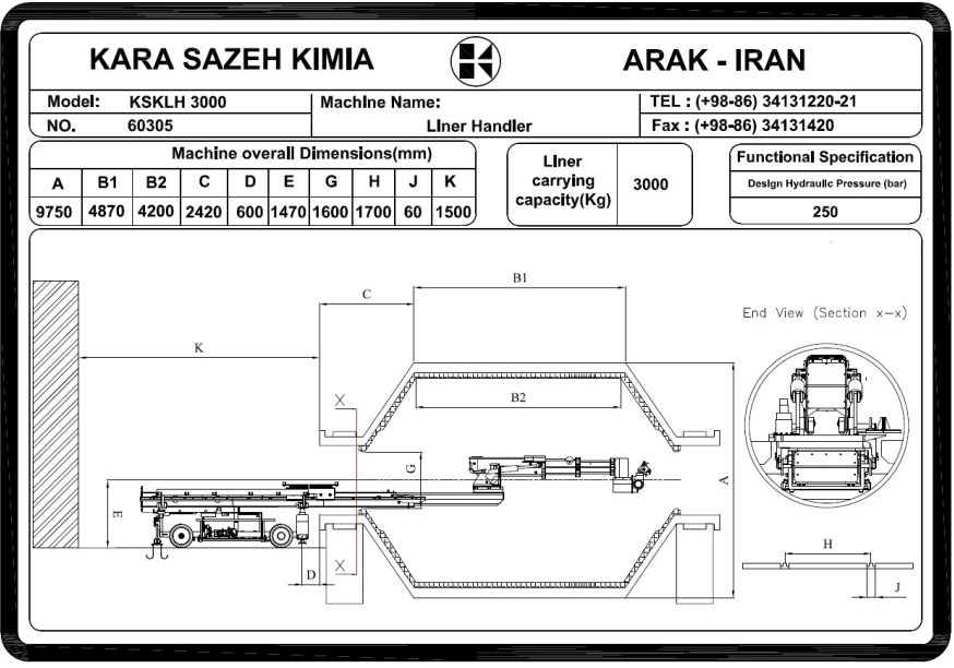
Mill Diameter (Inside Shell): ø9750 mm
Mill Length (Flange to Flange):4870mm
Maximum Liner weight :3000Kg
Existing maneuvering clearance:15000mm
Effective length:4200mm
Minimum clear entry diameter:ø1600mm
Mill axle to top of rail/floor:1470mm
Rail gauge:1700mm
part: Bodyt Hydraulic Driver & Suspension
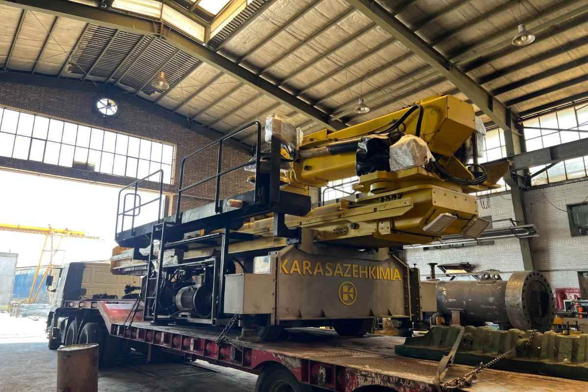

Efficient and Innovative Solutions for Liner Handler Project
1. Introduction
Kara Sazeh Kimia, as part of the Kara Knowledge-Based Industries Group, with 450 specialized personnel and over four decades of R&D activity, has successfully designed and manufactured more than 300 CNC industrial machines certified with European CE Marking. Some of these machines have been exported to European countries, including Germany and Italy, serving over 9,000 industrial customers in the domestic sales network.
The company is honored to cooperate with leading European companies such as DANIELI (Italy), SIEMENS, KRANBAU (Germany), as well as major Iranian industrial clients such as Foolad Sangon, Esfahan Steel, Mobarakeh Steel, Esfarayen Industrial Complex, Chadormalu, Golgohar, and Opal Parsian.
Furthermore, Kara Sazeh Kimia has more than seven years of technical cooperation, design, and manufacturing partnership with DANIELI Italy in steel plant construction. Our projects have been directly evaluated by Danieli’s Head Office in Italy, granting us the highest quality and execution class (Class D – the only holder in Iran).
Project Description – Design of Liner Handler Machine
Project Description – Design of Liner Handler Machine
In line with reducing overhaul time associated with Autogenous and Semi-Autogenous Mills (AG/SAG Mills), Kara Sazeh Kimia has developed the Liner Handler Machine to mechanize the process of transferring and replacing internal mill liners.
The core system, passing through the mill’s entry hatch, operates with pendulum, rotary, and reciprocating motions, allowing it to access and service various internal positions.
Project implementation steps include:
1. Conceptual and basic design based on liners with a maximum capacity of 3,000 kg
2. Mechanical and hydraulic modeling and calculations (referencing existing RME systems)
3. Detailed engineering: manufacturing drawings, assembly, installation plans, and bill of materials
4. Procurement and fabrication
5. Factory acceptance testing (FAT)
6. Loading and transportation
7. On-site commissioning
8. Operator training
9. Provision of spare parts list
10. Warranty and after-sales services
11. Maintenance and operation manuals
Dimensional specifications of the AG Mill are presented in the following figure. Additional options and modifications can be discussed and customized based on client requirements.
Machine Description
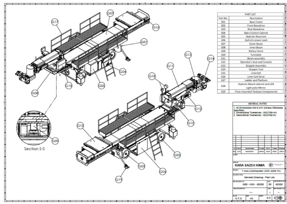
After connecting the power supply, the machine is positioned in front of the mill using its wheels and directional control system.
The actuators are controlled through two main valves, which are generally divided into chassis-mounted actuators and actuators related to Grapple movements.
On the main electrical panel, a power on/off switch and signal lamps are installed.
Another control panel includes a switch for enabling or disabling the two main valves.
An additional operator panel, located on the chassis platform, is dedicated to controlling the inner beam and liner cart movements according to the operator’s commands.
A wired remote control is also provided near the operator, equipped with three functions:
Emergency Stop
Horn (warning siren)
Enable Inner Beam
Once the machine is stabilized at the operation site with the help of stabilizers and base plates, the beam route is deployed in three stages. Using a hydraulic jack, the inner beam is extended, and the telescopic boom is inserted into the mill.
With the operator in position, the process of liner replacement operations can begin.
Warranty and After-Sales Services
1. The products are covered by a 2-year warranty starting from the date of delivery.
2. The after-sales service period is 10 years.
3. Operation and maintenance manuals will be provided by the seller.

